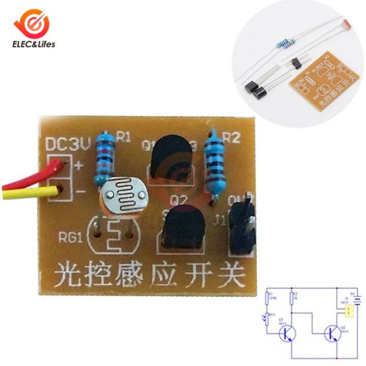
Light Control Sensor Switch Photoswitch Diy Kit Photosensitive Sensor Circuit Diagram
Light Control Sensor Switch Photoswitch Diy Kit Photosensitive Sensor Circuit Diagram Using this circuit, an electrical device or an appliance like a light bulb or a fan for example, can be controlled based on the intensity of the light near the circuit. Principle behind the Circuit The main principle of this circuit is based on the working of the LDR Sensor i.e. the Light Dependent Resistor and to switch ON or OFF the light
A tutorial on How to make a Light sensor circuit and Darkness detector circuit using LDR and transistor, along with detailed explanation on how the circuit w

Light Activated Switch Circuit using LDR Sensor Circuit Diagram
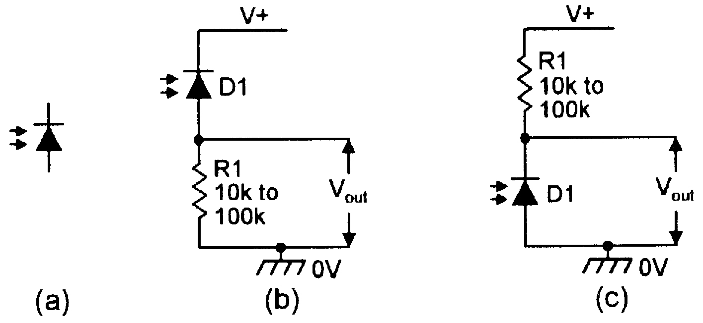
Step 11: Connect the Power Supply and the Circuit is Now Ready! How This Circuit Works. First things first: The resistance of LDR (Light Dependant Resistor) is inversely proportional to the intensity of light falling on it. It implies that if the intensity of incident light is high, the resistance of LDR will be less and vice versa.

A light sensor switch circuit is an electronic device that detects the presence or absence of light and triggers a corresponding action, such as turning a device on or off. With a little practice and experimentation, you can create custom light sensor circuits tailored to your specific needs and requirements. Related posts: The Importance
Light Sensor Switch Circuit: A Guideline in Building your Sensor ... Circuit Diagram
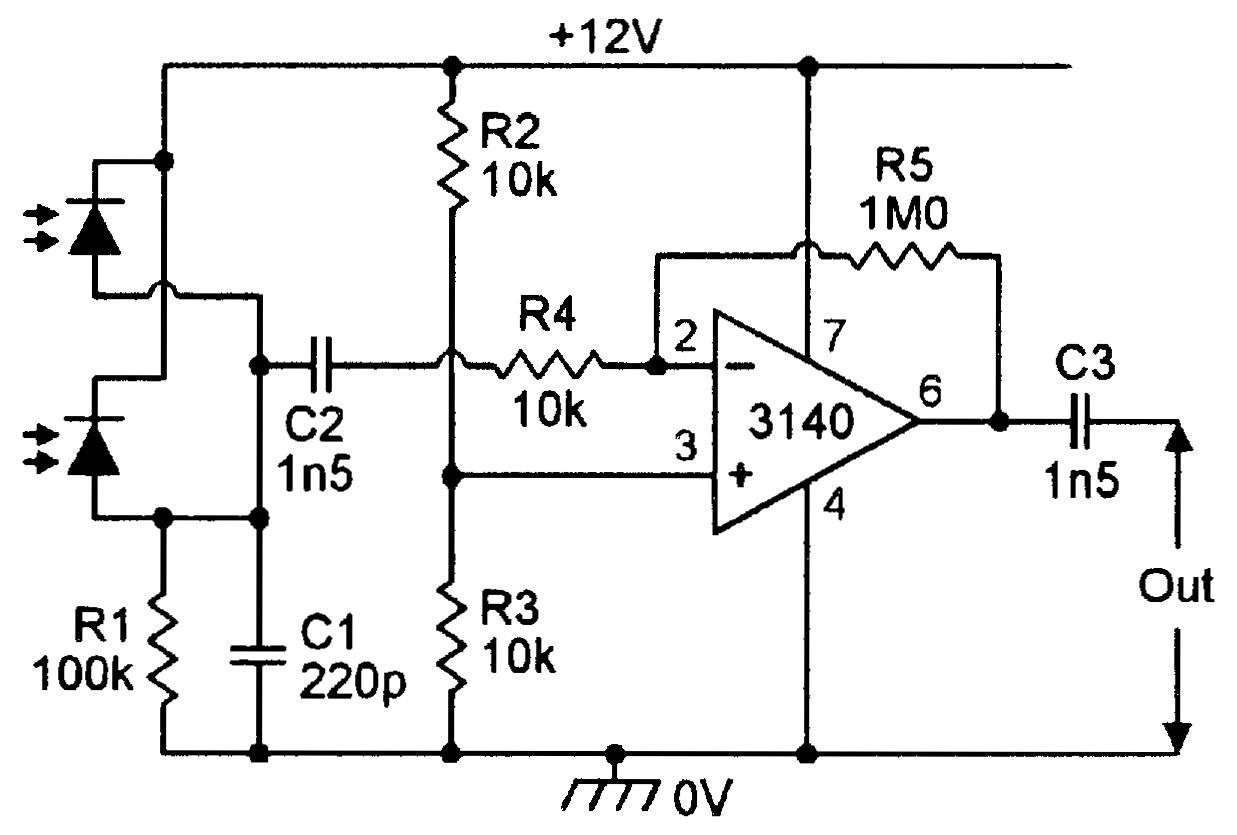
The light-sensitive switch circuit using the op-amp 741 presents an efficient solution for automating lighting systems based on ambient light conditions. By integrating the capabilities of the op-amp and the light-dependent resistor, this circuit enables seamless and intelligent control over the connected lighting load. Welcome to our YouTube tutorial on creating a light sensor circuit using an LDR (Light Dependent Resistor) and an IC 741 Op Amp. In this video, we will guide